Description of the Remote Continuous GPS Station Package

J. Galetzka (Caltech), S. Dockter, D. Elliott, and F. Wyatt (UCSD-SIO), K. Hudnut (USGS Pasadena), and M. Jackson (UNAVCO)

Introduction
The Southern California Integrated GPS Network (SCIGN) consortium has developed the Remote Continuous GPS Station Package (RCGSP) as a method to collect high-precision geodetic data relatively rapidly and inexpensively in very remote locations. The centerpiece of the RCGSP is the shallow drilled-braced monument, a stainless steel quadpod anchored 1 to 2.25 meters into the earth. Developed in the days following the 16 October, 1999 Mw 7.1 Hector Mine earthquake, the RCGSP enabled geophysicists to capture post-seismic deformation in a remote region of California's Mojave Desert that had little GPS station coverage.

Although the initial focus of development was rapid deployment of autonomous continuous GPS stations by helicopter, it quickly became clear that the RCGSP was, compared to other continuous GPS station types, relatively inexpensive and easy to transport, build, operate and maintain with minimal impact to the surrounding environment. Additionally, data collected at these stations has proved to have high repeatability and precision.

Figure 1 View of the continuous GPS station at Jomsom, Nepal showing monument assembly in the left foreground and mast assembly in the right background.

The RCGSP consists of two components--the monument assembly and the mast assembly--typically spaced about 7 meters apart, anchored into bedrock and having good sky view (see figure 1). The two assemblies are connected by a coaxial cable protected in buried conduit. Power to the station is provided by solar panels and telemetry is wireless. Installation time at the site is anywhere from 8 to 32 hours depending on the size and training of the installation crew and/or the local site conditions such as weather and dense vegetation cover.

Refinements in the installation method and advances in technology since the first RCGSP was deployed at Rodman Mountain, San Bernardino County, California (site code RDMT) on 24 November, 1999 have made RCGSP even smaller and easier to deploy with increased monument stability, making the RCGSP a world class system for monitoring crustal deformation in almost any environment. The geodetic monument can now be found in GPS stations throughout the western United States, Alaska, Saudi Arabia, the Galapagos Islands, Mexico and Indonesia.

Components of the Remote Continuous GPS Station Package

The Remote Continuous GPS Station Package (RCGSP) consists of two components: the monument assembly and the mast assembly. The two assemblies occupy a rectangular space about 2 meters wide by 10 meters long. To avoid noisy data and reduced solar panel output, the GPS station should be placed away from buildings and cleared of vegetation in a circle at least 25 meters in diameter with the monument assembly near the center of this circle.

Figure 2
Monument assembly with radome removed.
Figure 3
Close up view of a 3-meter high mast assembly.


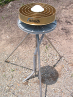
The monument assembly (see figure 2) is a stainless steel quadpod (called a shallow drilled braced monument) anchored 2.25 meters into bedrock, onto which a geodetic-grade GPS antenna, enclosed in a protective polycarbonate radome, is fixed. The finished assembly stands about 1.4 meters above the surface.

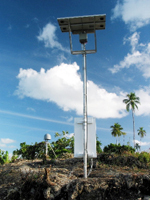
The mast assembly (see figure 3) consists of: a 0.75 m high x 0.4 m wide x 0.4 long aluminum enclosure, which contains two deep-cycle gel-cell batteries, a solar power controller, a dual-frequency GPS receiver and a telemetry device; a 1 m x 1 m array of solar panels; and a small telemetry antenna. The enclosure, solar array and radio antenna are mounted on a 6.35 cm diameter metal pole standing 2 to 3 meters high.

All components of the RCGSP have been designed to resist theft and vandalism, and, in general, the GPS site does not need to be fenced.

Installation Method

The philosophy behind the RCGSP tools, materials and architecture is that they be as compact, lightweight, efficient and dependable as possible in order to make high-quality GPS station installations fast and easy. Electricity to operate power tools is provided by portable gasoline-powered generators.

Once a site has been selected, tools, materials and a small installation team can be transported to the site by helicopter, truck or boat. If such vehicles are not available, porters or pack animals can transport the tools and materials to a remote site.

The key tools in the installation are an electric hammer-drill and a 1.5-inch diameter x 96-inch long drill bit used to prepare holes that the monument and mast assemblies will be anchored into. To construct a shallow drilled braced monument, four 2.25-meter holes, one vertical and three diagonal, are drilled into bedrock. The legs of the monument are made of 1-inch diameter stainless steel rod. The legs are anchored into the holes using epoxy then welded together where they converge about 1.1 meters above the ground surface. A special leveling adapter securely attaches the GPS antenna to the monument and supports a gray protective radome.

The pole for the mast assembly is anchored to a depth of 1 meter. The solar array and instrument/battery enclosure are easily wired and configured once the pole is stable.

Nearby trees, tall shrubs and grass will be cut and cleared to provide clear sky-view for the GPS and AceS antennas.

Maintenance

The Remote Continuous GPS Station Package has shown to be highly reliable.

Problems with a station can usually be identified by the quality and quantity of the GPS data generated, however, an annual inspection of each site in the network should be made to ensure proper operation, check for storm damage or vandalism, and ensure vegetation is not obscuring sky view of the GPS antenna or solar array. New evidence shows that GPS signals are sensitive to the presence of vegetation surrounding a continuous GPS station, so it is highly essential to maintain the original sky view when the station was first created. The two deep-cycle gel-cell batteries in each station may have to be replaced every five to ten years.


© Tectonics Observatory :: California Institute of Technology
Last updated: July 20, 2009 :: Contact Us


Tectonics Observatory